Why Astra Signal Quality Changes Across Frequencies
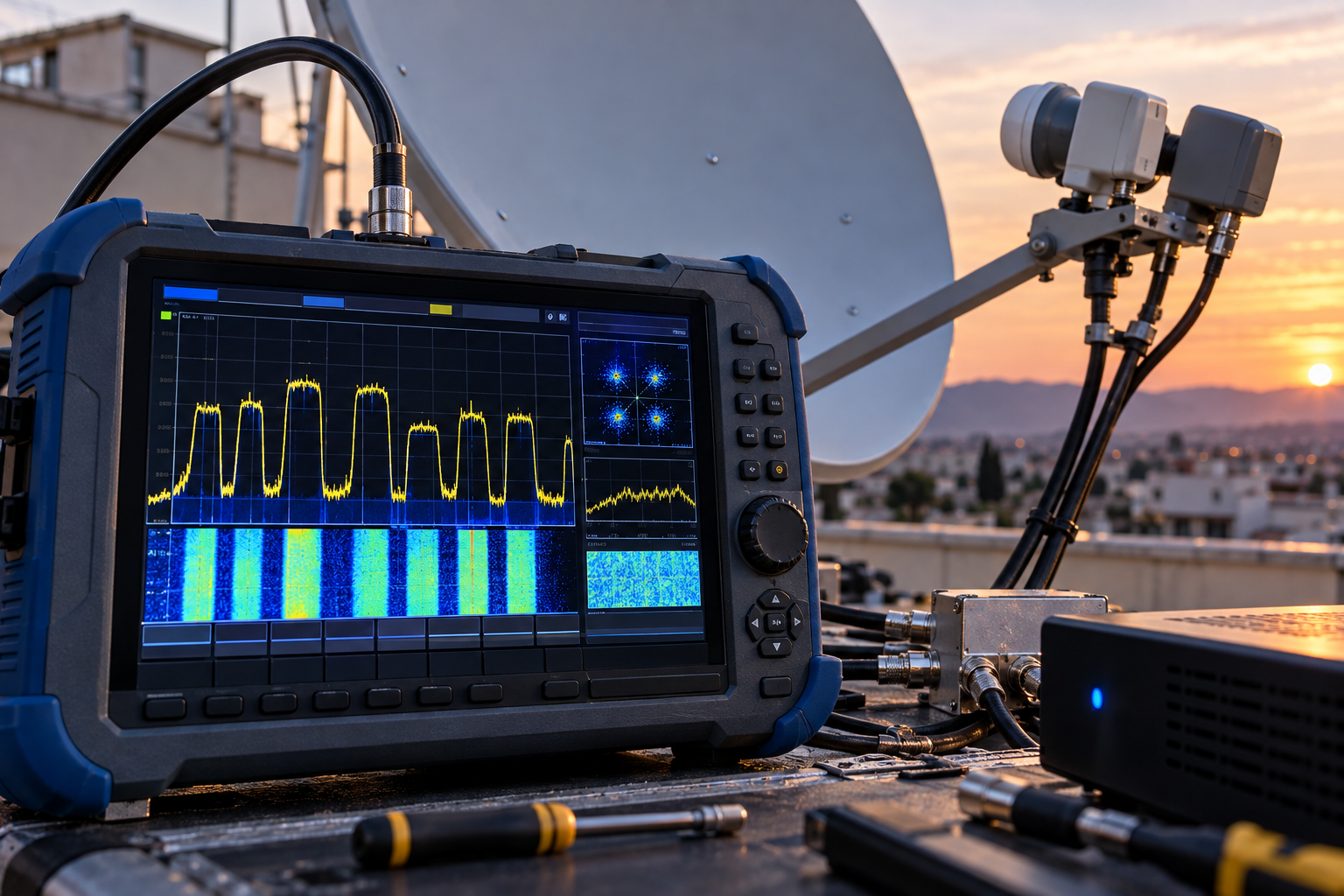
One Astra 19.2E frequency shows excellent signal quality. Another, received through the same dish, LNB and coaxial cable, barely stays locked. A third works normally until the weather changes. If the equipment is identical, why can the receiver report such different results across transponders?
The answer is that satellite reception is not determined by antenna size alone. Each carrier has its own received power, noise and interference conditions, transmission parameters, and decoding requirements. The receiving equipment also behaves differently across frequencies. To understand whether the variation is normal or indicates a fault, you need to look beyond the receiver’s signal-quality percentage and examine what happens to the actual reception margin.
Astra 19.2E signal quality can vary across frequencies because different transponders may use different satellite beams, power levels, modulation schemes and forward error correction settings. The LNB, dish, coaxial cable and receiver can introduce additional frequency-dependent effects. A difference in displayed quality percentages is not automatically a problem; the important question is whether each carrier has enough margin for reliable decoding.
Why Astra Transponders Have Different Reception Margins
A satellite receiver does not receive one uniform Astra signal containing every television channel.
It receives individual radio-frequency carriers transmitted by satellite transponders. Each carrier has its own technical characteristics and reception conditions.
Those characteristics can include:
- Satellite beam coverage and effective radiated power
- Carrier frequency and polarization
- Modulation format
- Forward error correction rate
- Noise and interference conditions
- Required demodulator performance
Even when two carriers originate from the same orbital position, they do not necessarily have identical link budgets.
The link budget describes the gains and losses between the satellite transmitter and the receiving system.
It includes transmitted power, antenna characteristics, propagation losses, receiving antenna gain and noise performance.
The resulting reception margin determines how much additional impairment a carrier can tolerate before reliable decoding fails.
That is why a single Astra installation may have substantial margin on one transponder and very little on another.
For a related explanation, see Why Astra 19.2E Works but Some Transponders Fail.
Satellite Beam and EIRP Differences
Astra 19.2E is an orbital position used by multiple satellite payloads and beams.
Not every carrier necessarily reaches a particular receiving location with the same power density.
One of the important quantities used in satellite coverage planning is Effective Isotropic Radiated Power (EIRP).
EIRP expresses the transmitted power together with the transmitting antenna’s directional gain, referenced to an ideal isotropic radiator.
Satellite coverage maps often use EIRP contours to indicate expected signal levels across geographic regions.
If two Astra carriers use different beams, their received power at a particular location may differ even when the receiver uses the same dish.
A carrier transmitted through a beam with stronger coverage at your location may provide more available margin.
Another carrier may be closer to the edge of its beam or subject to different transmission conditions.
However, the EIRP contour alone does not determine whether a channel will decode reliably.
Modulation, coding, antenna gain, noise temperature and other link-budget factors also matter.
It is therefore inaccurate to assume that every transponder at 19.2E should produce identical quality readings.
How LNB Performance Changes Across Frequencies
The Low-Noise Block downconverter is responsible for receiving and converting Ku-band satellite signals into an intermediate-frequency range suitable for the tuner.
Its performance is not necessarily perfectly flat across its operating bandwidth.
Relevant characteristics include:
- Conversion gain
- Noise performance
- Local oscillator stability
- Frequency response
- Polarization isolation
- Linearity under the combined received signal load
A well-designed LNB should provide suitable performance throughout its specified operating range, but real devices have tolerances and variations.
An aging or defective LNB may exhibit greater frequency-dependent problems.
For example, some carriers may remain stable while others show reduced MER or fail to lock.
It is important to distinguish LNB gain from actual signal quality.
Higher conversion gain does not automatically mean better reception.
If the receiver already receives sufficient signal level, additional gain may provide little benefit. Excessive gain can even create problems if it overloads downstream equipment.
Noise performance, linearity and the complete receiving system are more meaningful than gain alone.
When comparing LNBs, do not assume that a lower advertised noise-figure number guarantees better real-world performance. Product specifications and test methods can vary.
Why Coaxial Cable Loss Is Frequency-Dependent
The coaxial cable carries the LNB’s intermediate-frequency output to the satellite receiver.
For a conventional universal Ku-band LNB, the receiver commonly tunes signals within an IF range around 950–2150 MHz.
Coaxial attenuation generally increases with frequency.
That means two satellite carriers can experience different cable losses after frequency conversion, even though they travel through the same cable.
A longer cable or a cable with poor shielding, damaged connectors or water ingress can make this effect more noticeable.
However, there is an important distinction:
Cable attenuation reduces signal level, but it does not necessarily reduce C/N by the same amount.
When the receiver has sufficient input level and an appropriate noise performance, a moderate reduction in level may not significantly affect demodulation.
Problems become more likely when the loss pushes the tuner toward its sensitivity limits, when impedance mismatches create frequency-selective impairments, or when interference and noise become significant.
Therefore, a weak receiver strength reading at one IF frequency does not automatically prove that the carrier has poor MER.
Technical distinction: Satellite downlink frequency and receiver intermediate frequency are not the same thing. Cable attenuation depends on the IF frequency carried through the coaxial cable, which is determined by the satellite carrier frequency and the LNB’s selected local oscillator.
MER, C/N and Signal Strength: What They Really Measure
Many satellite receivers display two familiar indicators: Signal Strength and Signal Quality.
Unfortunately, those percentages are not standardized across receiver brands.
A value of 80% on one receiver does not necessarily represent the same RF condition as 80% on another.
For professional diagnosis, several measurements are more useful.
Signal Level
Signal level describes the power reaching the receiver input or another measurement point.
It can help identify excessive attenuation, weak LNB output or distribution problems.
However, strong signal level alone does not guarantee correct decoding.
Carrier-to-Noise Ratio (C/N)
C/N compares the carrier power with noise power over a defined measurement bandwidth.
It helps characterize the signal’s relationship to noise, but measurement conditions and bandwidth must be considered.
Modulation Error Ratio (MER)
MER measures the quality of the received modulation constellation by comparing ideal symbol positions with measured symbol errors.
It reflects the combined impact of impairments such as noise, interference and distortion.
For digital satellite reception, MER is particularly useful because it provides information about how accurately the demodulator receives the transmitted symbols.
Bit Error Rate (BER)
BER describes the proportion of bits received incorrectly at a defined stage of the decoding process.
In DVB-S2 systems, measurements taken before and after error correction represent different points in the receiver’s processing chain.
They should not be compared without knowing where the measurement is taken.
| Measurement | What It Describes | Main Limitation |
|---|---|---|
| Signal level | RF power at a measurement point | Does not directly establish modulation quality |
| C/N | Carrier power relative to noise | Depends on measurement conditions and bandwidth |
| MER | Received modulation accuracy | Must be interpreted with the transmission mode |
| BER | Bit errors at a specified decoding stage | Different measurement stages are not interchangeable |
| Receiver quality percentage | Manufacturer-defined indication | Not standardized across devices |
For a deeper explanation, read Why Signal Quality Matters More Than Signal Strength.
How DVB-S2 Modulation and FEC Affect Quality Readings
Not every Astra transponder uses the same modulation and coding configuration.
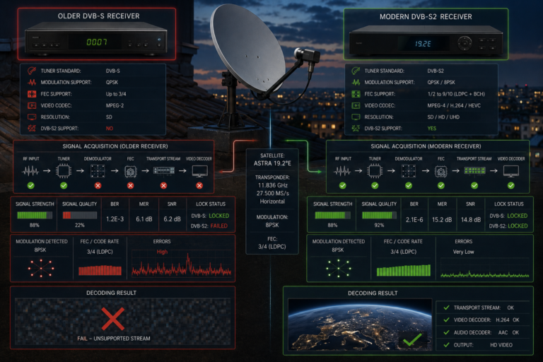
DVB-S and DVB-S2 support different transmission modes, and DVB-S2 carriers may use modulation formats such as QPSK or 8PSK.
Forward Error Correction (FEC) adds redundancy that allows the receiver to correct certain transmission errors.
The combination of modulation and coding determines the robustness and spectral efficiency of the transmission.
In general, a transmission mode designed for higher spectral efficiency may require better reception conditions than a more robust mode.
However, the actual threshold depends on the complete modulation and coding configuration, receiver implementation and measurement method.
It is therefore misleading to assign one universal MER threshold to every Astra transponder.
Another complication is how receiver manufacturers calculate their quality percentages.
Some receivers may derive the displayed percentage from estimated demodulation margin, error measurements or other internal indicators.
Two carriers with similar measured MER can therefore show different quality percentages if they use different transmission modes.
This does not necessarily mean one carrier is physically stronger.
It may mean that the receiver is expressing the available decoding margin differently.
Polarization Isolation and LNB Skew
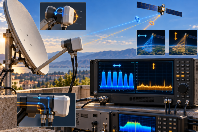
Astra television transmissions commonly use horizontal and vertical linear polarization.
The LNB must be oriented correctly to separate the wanted polarization from the unwanted one.
This rotational adjustment is known as LNB skew.
Incorrect skew can reduce cross-polarization isolation and allow more energy from the opposite polarization to interfere with the wanted carrier.
The resulting impairment may affect some transponders more than others.
For example, a carrier may experience more interference from an opposite-polarization transmission with an overlapping or nearby frequency.
Another carrier may remain relatively unaffected.
This can create a pattern in which signal quality varies significantly between frequencies even though the LNB receives them through the same dish.
Skew should be set according to the receiving location and satellite geometry, then optimized using appropriate measurements where necessary.
Do not rotate the LNB randomly to improve one transponder without checking the effect on others.
Dish Gain, Alignment and Frequency Response
A satellite dish does not provide exactly the same gain at every frequency.
For a fixed physical aperture and comparable efficiency, antenna gain generally increases as wavelength decreases.
However, real antenna performance also depends on reflector accuracy, feed illumination, alignment and efficiency.
A dish that is slightly misaligned may still provide enough margin for stronger carriers while leaving weaker ones near their decoding thresholds.
This does not mean the dish is aligned differently for each transponder.
It means the available margin differs, so the same pointing error can have different practical consequences.
Feed positioning also matters.
If the LNB is incorrectly positioned relative to the reflector’s focal region, antenna efficiency may decrease.
Some carriers may continue working because they have sufficient margin, while others become unstable.
For more on alignment-sensitive reception, see Why Some Astra Frequencies Need Better Alignment.
Why Interference Can Affect Individual Frequencies
Not every signal-quality difference is caused by weak satellite power.
Interference can affect individual carriers or frequency ranges.
Possible sources include:
- Cross-polarization interference
- Adjacent-carrier interference
- Local electromagnetic interference entering poorly shielded equipment
- Impedance mismatches and reflections in the coaxial system
- Nonlinear distortion or overload in receiving equipment
For example, a poorly shielded cable or connector may allow unwanted energy to enter the IF signal path.
If that interference overlaps a particular intermediate-frequency range, some satellite transponders may suffer more than others.
Similarly, reflections caused by impedance mismatches can create frequency-selective response variations.
These effects are not necessarily visible as a simple reduction in signal-strength percentage.
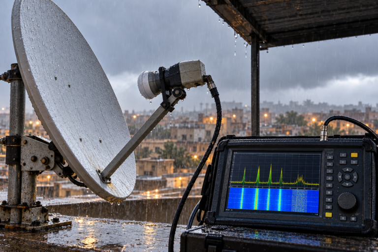
A professional spectrum analyzer and modulation-quality meter can help distinguish carrier-level problems from noise, interference and distortion.
Why One Astra Frequency Fails Before Another
Digital satellite reception has a threshold-like behavior.
As long as the demodulator receives sufficient signal quality for the selected modulation and coding mode, error correction can maintain a usable transport stream.
When the reception conditions deteriorate beyond that operating margin, uncorrectable errors can rise rapidly.
The result may be pixelation, audio interruptions, freezing or complete loss of carrier lock.
Two transponders can therefore respond very differently to the same additional impairment.
Consider the following simplified example.
Transponder A has an estimated 5 dB of margin above its required decoding condition.
Transponder B has only 1.5 dB of margin.
If both experience an additional 2 dB degradation, Transponder A retains approximately 3 dB of margin, while Transponder B falls below its required operating condition.
These values are illustrative only. They are not measurements of specific Astra transponders and should not be used as universal DVB-S2 thresholds.
This explains why one Astra frequency may continue working during rain or minor reception degradation while another fails.
The difference is not necessarily a defective transponder.
It may simply have less available margin under the current receiving conditions.
For a related example, see Why One Astra Transponder Breaks Up in the Rain.
How to Compare Astra Transponders Properly
Comparing transponders requires more than looking at two receiver percentage bars.
Start by selecting several current, verified Astra 19.2E carriers.
Choose carriers that represent different frequencies, polarizations and, where relevant, transmission modes.
Record the following information:
- Carrier frequency
- Polarization
- Symbol rate
- Transmission standard and modulation
- Measured signal level
- MER or C/N, where available
- Error measurements and carrier-lock status
- Weather and installation conditions
Use the same measurement instrument and consistent settings wherever possible.
Do not compare a percentage displayed by one receiver with a percentage from another brand and assume the values represent the same quantity.
Also avoid comparing MER values without considering the different modulation and coding modes.
The most useful comparison is often the available margin relative to the operating requirements of each carrier.
A transponder with lower absolute MER may still operate reliably if its transmission mode is sufficiently robust.
Conversely, a carrier with apparently respectable MER may have little margin if its selected mode requires better conditions.
Normal Variation or Equipment Fault?
| Observed Pattern | Possible Explanation | Recommended Check |
|---|---|---|
| Different quality percentages but all channels work | Normal variation or different receiver quality calculations | Compare actual lock and error performance |
| One polarization is consistently weaker | Skew, polarization isolation or switching issue | Compare H and V carriers and inspect LNB orientation |
| Quality deteriorates across a range of IF frequencies | Cable attenuation, impedance mismatch or equipment response | Measure the IF path and inspect connectors |
| Only one carrier has poor MER | Carrier-specific margin or interference problem | Compare spectrum and modulation quality |
| Several weak carriers improve after careful alignment | Insufficient antenna pointing margin | Optimize alignment using appropriate measurements |
| One frequency fails during rain while others survive | Different fade margins | Compare clear-sky margin and rain behavior |
| Quality changes after the LNB warms up | Possible temperature-sensitive component fault | Observe repeatable behavior and test a compatible LNB |
These patterns are diagnostic clues, not definitive diagnoses.
Several faults can produce similar symptoms, so measurements and controlled testing remain important.
Step-by-Step Troubleshooting
Step 1: Verify the Actual Satellite
Confirm that the dish and switching system are receiving Astra 19.2E.
The satellite name displayed in the receiver menu does not independently prove the physical orbital position.
Step 2: Select Known Transponders
Use current verified carrier parameters from a reliable source.
Avoid diagnosing the installation using outdated transponder entries.
Step 3: Record the Failure Pattern
Determine whether the problem affects one frequency, one polarization, one band, or a broader frequency range.
Step 4: Compare Measurements Correctly
Where possible, record MER, C/N, signal level and error performance using the same instrument.
Treat receiver quality percentages as approximate indicators rather than calibrated measurements.
Step 5: Inspect LNB Skew and Feed Position
Incorrect orientation or feed positioning can reduce antenna performance and cross-polarization isolation.
Do not disturb a correctly aligned installation without evidence that adjustment is necessary.
Step 6: Inspect the Coaxial Signal Path
Check accessible connectors, cable condition, wall plates and distribution equipment.
Power off equipment before disconnecting coaxial cables.
Step 7: Check for Frequency-Selective Problems
If the degradation follows IF frequency rather than satellite polarization or beam, investigate cable response, connectors and downstream equipment.
Step 8: Consider LNB Performance
If other causes have been excluded, test with a known-good compatible LNB.
Do not assume that a higher-gain replacement will automatically improve modulation quality.
Step 9: Evaluate Reception Margin
Determine whether the affected carriers have enough margin for reliable operation under expected weather conditions.
A carrier that barely works in clear weather may fail during relatively modest additional attenuation.
Step 10: Make One Change at a Time
Record measurements before and after each adjustment.
Changing the dish alignment, LNB, cable and receiver settings simultaneously makes it difficult to identify the real cause.
Reality Check
Different Astra signal-quality readings do not automatically mean that the dish or LNB is defective.
Transponders can have different received power levels, beam characteristics, modulation requirements and reception margins.
At the same time, the receiving installation may introduce frequency-dependent losses, interference or polarization-related impairments.
Receiver quality percentages are not standardized measurements and should not be used as the sole basis for comparing transponders.
Reliable diagnosis requires distinguishing signal level from modulation quality and interpreting MER, C/N and error performance in the context of each carrier’s transmission mode.
The important question is not whether every frequency displays the same percentage. It is whether every required carrier has sufficient margin for stable decoding.
Final Verdict
Astra 19.2E signal quality changes across frequencies because each transponder has its own transmission characteristics and reception margin, while the receiving system introduces additional frequency-dependent effects.
Different satellite beams, EIRP levels, modulation schemes and coding rates can produce different operating conditions.
LNB response, coaxial attenuation, dish alignment, polarization isolation and interference can further influence the result.
A strong signal-level reading does not guarantee good MER, and a high receiver quality percentage does not necessarily represent a calibrated measurement.
To identify a real fault, compare verified carriers using consistent measurements and examine whether the problem follows a particular frequency range, polarization, transmission mode or physical signal path.
If all required transponders decode reliably with adequate margin, different quality readings may be entirely normal.
If one or more carriers approach their decoding limits, the solution is to identify the factor reducing their margin rather than attempting to make every receiver percentage identical.
Frequently Asked Questions
| Question | Answer |
|---|---|
| Why is Astra signal quality different on each frequency? | Different transponders can have different beam power, modulation requirements, noise conditions and reception margins. Equipment response can also vary with frequency. |
| Should every Astra 19.2E transponder show the same signal quality? | No. Identical readings are not expected, and receiver quality percentages are not standardized across devices. |
| Can an LNB cause some Astra frequencies to be weaker? | Yes. Frequency response, noise performance, oscillator problems or faults can affect certain carriers more than others. |
| Does a longer coaxial cable affect some frequencies more? | Yes. Cable attenuation generally increases with intermediate frequency, although the effect on decoding depends on the complete signal path. |
| What is more useful: signal strength or MER? | MER is generally more informative about digital modulation quality, while signal level remains useful for diagnosing attenuation and input-power problems. |
| Can wrong LNB skew affect individual transponders? | Yes. Poor polarization alignment can increase interference from the opposite polarization and degrade some carriers more than others. |
| Why does one Astra frequency break up during rain? | It may have less available fade margin than other carriers, causing it to cross its decoding threshold sooner. |
| Does a higher-gain LNB always improve signal quality? | No. Additional gain does not necessarily improve C/N or MER and can create overload problems in some receiving systems. |
| Can dish misalignment affect some frequencies more than others? | Yes. A common pointing error reduces available antenna performance, but carriers with smaller margins may fail first. |
| How can I compare Astra transponders accurately? | Use current verified carrier parameters and compare signal level, MER, C/N, error performance and lock status under consistent measurement conditions. |