Why Astra 19.2E Signal Drops on One Polarization
Astra 19.2E can produce one of the most useful fault patterns in satellite troubleshooting: channels on one polarization remain completely stable while many channels on the other polarization become weak, freeze or disappear. When that happens, the satellite itself is rarely the first place to look.
Horizontal and vertical satellite signals share the same dish, cable and receiver, but the LNB must separate and select them correctly. Receiver voltage, LNB skew, coaxial resistance, connectors and multiswitch equipment can therefore create a fault that affects one polarization much more than the other. Recognizing this pattern can save hours of unnecessary dish adjustment.
If several missing Astra transponders share the same polarization, treat that as diagnostic evidence. A polarization-specific pattern can point toward the LNB and its control path rather than a general loss of Astra 19.2E reception.
- Why Satellite TV Uses Two Polarizations
- How Your Receiver Selects H or V
- Why 13V and 18V Matter
- How Cable Voltage Drop Can Cause Trouble
- Why LNB Skew Matters
- How an LNB Can Lose One Polarization
- Why F-Connectors Can Create Selective Failures
- Multiswitch Systems Add Another Failure Point
- Can the Receiver Cause the Problem?
- Do Not Confuse Polarization With Band Switching
- Can Dish Alignment Affect One Polarization More?
- Use MER and BER to Compare H and V
- How to Diagnose the Problem Step by Step
- Reality Check
- Final Verdict
- FAQ
Why Satellite TV Uses Two Polarizations
Satellite operators need to use available spectrum efficiently. One technique is polarization reuse.
Signals can be transmitted using different polarization orientations, commonly identified in European Ku-band television reception as horizontal and vertical.
This allows carriers using opposite polarizations to coexist within the overall frequency plan while the receiving antenna system separates them sufficiently for reliable demodulation.
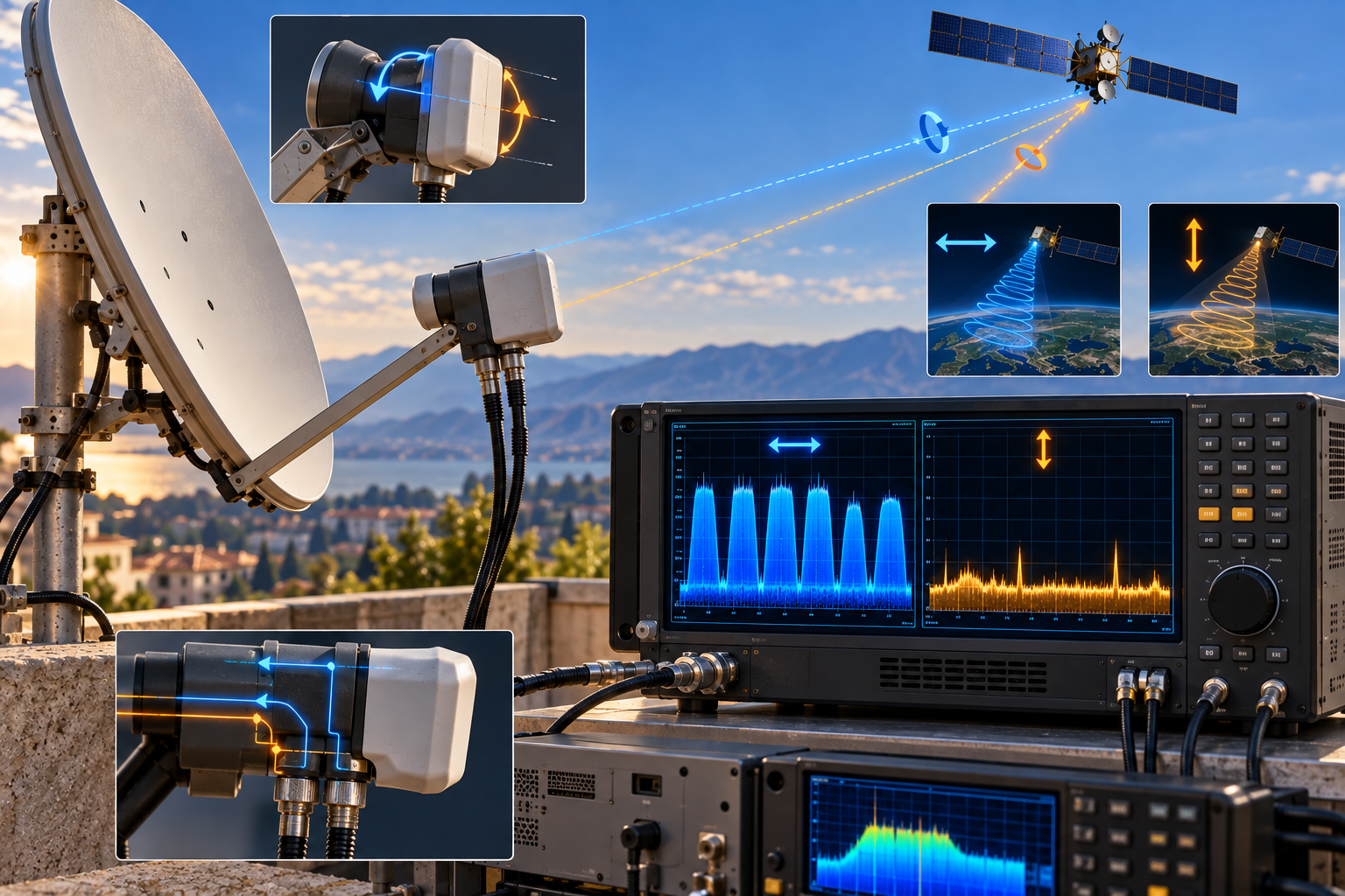
Your dish reflector itself does not electronically switch between horizontal and vertical channels. It concentrates the incoming RF energy toward the feed.
The LNB is responsible for receiving the appropriate polarization and converting the Ku-band signal into the lower intermediate-frequency range sent through the coaxial cable.
This is why a polarization-specific problem immediately makes the LNB and its control system important suspects.
How Your Receiver Selects H or V
A normal single-cable satellite connection has an interesting engineering challenge.
The receiver needs to tell the outdoor LNB which reception state it wants, but there is usually no separate control cable running to the dish.
Instead, control information and electrical power share the same coaxial cable that carries the satellite IF signal back to the receiver.
For polarization selection in a conventional universal-LNB system, the receiver changes the DC supply voltage delivered through the coax.
The LNB detects that voltage and selects the appropriate polarization state.
Approximately 13 volts is commonly associated with vertical polarization selection, while approximately 18 volts is commonly associated with horizontal polarization selection in conventional universal-LNB systems.
These values describe the normal control principle. Real measured voltage can vary somewhat depending on equipment design, cable resistance, load and where the measurement is taken.
The important point is that polarization selection depends on an electrical control path from the receiver all the way to the LNB.
Why 13V and 18V Matter
Imagine a receiver successfully supplies the lower polarization-selection voltage but cannot deliver the higher state correctly under load.
The LNB may remain in the wrong polarization state even though the user selects a horizontal transponder.
The receiver then attempts to tune a carrier that is not actually being delivered through the selected LNB path.
Depending on the installation and nearby carriers, the user may see zero quality, unstable reception or confusing signal-meter behaviour.
This can make the problem look like missing Astra frequencies when the actual failure is polarization switching.
The opposite type of fault is also possible. The exact behaviour depends on the receiver, LNB and distribution equipment.
That is why the first diagnostic question should not be “Are channels missing?” but rather:
Do the missing transponders share the same polarization?
How Cable Voltage Drop Can Cause Trouble
Coaxial cable carries both RF and DC power in a conventional satellite installation.
Every cable has electrical resistance.
As current flows toward the LNB, some voltage is lost along the path. With good cable, proper connectors and reasonable distances, the system is designed to tolerate this.
Problems begin when resistance becomes excessive.
A very long cable run, poor-quality coax, damaged copper conductors, corroded connectors or bad joints can increase voltage drop.
A receiver may output the expected control voltage at its tuner connector, yet the voltage reaching the LNB can be lower.
This becomes particularly interesting when a system sits near the LNB’s switching threshold.
One polarization state may continue working while the other becomes unreliable.
| Observed Pattern | Possible Area to Investigate |
|---|---|
| Vertical works, horizontal fails | Voltage delivery, receiver supply, cable, connectors, LNB or multiswitch |
| Horizontal works, vertical fails | LNB switching, receiver control, distribution path or LNB fault |
| Both polarizations weak | General alignment, dish size, LNB, cable loss or low overall margin |
| Only one receiver has the problem | Receiver output, local cable or individual distribution output |
| All receivers lose the same polarization | Shared LNB or distribution infrastructure becomes more suspicious |
Why LNB Skew Matters
Voltage selects the polarization path, but the physical orientation of the LNB also matters.
LNB skew is the rotational position of the feed relative to the polarization orientation of the arriving signal.
The ideal orientation depends on the geometry between the receiving location and the satellite position.
If the LNB is badly rotated, the wanted polarization may not be separated as cleanly from the opposite polarization.
This reduces cross-polarization isolation.
The receiver can then see more unwanted energy from the opposite polarization, degrading the quality of the wanted carrier.
The result is not always total signal loss. More often, poor skew reduces the available margin.
Strong transponders can continue working while weaker or more demanding carriers become unstable.
This is why skew should be optimized using quality measurements rather than simply positioning the LNB so that it “looks straight.”
How an LNB Can Lose One Polarization
An LNB can fail partially.
This is an important concept because users often assume an LNB is either completely functional or completely dead.
Internally, the device must receive the incoming microwave energy, select the required polarization and band, amplify the signal and perform frequency conversion.
A fault affecting polarization selection can therefore leave a large part of the system working normally.
You may still receive dozens or hundreds of services, creating the impression that the LNB cannot possibly be responsible.
Yet every missing carrier may share the same polarization.
Ageing electronics, moisture, corrosion, internal switching problems or temperature-sensitive components can all create partial failures.
If swapping the LNB with a known-good compatible unit restores the missing polarization without changing dish alignment, that is strong diagnostic evidence.
However, replacing the LNB should come after basic cable, connector and receiver checks rather than being the automatic first step.
Why F-Connectors Can Create Selective Failures
The small F-connectors on a satellite installation are easy to underestimate.
A poor connector can affect both RF transmission and the DC/control path.
If the centre conductor is oxidized, loose or making poor contact, resistance can increase. If shielding strands contact the centre conductor, the system can become unstable or short-circuited.
Outdoor connectors are especially vulnerable to moisture when weather sealing is poor.
Water entering the coax can also alter RF performance and eventually damage the cable.
Because polarization switching relies on voltage reaching the LNB correctly, a connector fault can create symptoms that appear unrelated to the connector itself.
If an entire polarization disappears suddenly, inspect the simple parts before moving the dish. A damaged connector can imitate a much more complicated satellite fault.
Multiswitch Systems Add Another Failure Point
Large installations often use multiswitches instead of connecting each receiver directly to a simple universal LNB.
These systems distribute different satellite polarization and band combinations to multiple users.
That creates more precise diagnostic patterns.
If every apartment connected to a system loses the same Astra polarization or polarization/band combination, the fault may exist in a shared LNB feed, trunk cable, amplifier or multiswitch input.
If only one subscriber loses those channels, the common satellite feed may be perfectly healthy.
The fault could instead be at one multiswitch output, one cable run, wall socket or receiver.
Comparing affected outlets is therefore extremely valuable.
Do not adjust a shared rooftop dish because one apartment cannot receive horizontal transponders while every other apartment can.
Can the Receiver Cause the Problem?
Yes.
The receiver or television tuner is responsible for supplying power and control to a directly connected universal LNB.
A fault in its LNB power circuit can prevent correct polarization switching.
This is easy to investigate when another compatible receiver is available.
Connect the same satellite feed to the second receiver and test known transponders on both polarizations.
If both polarizations immediately work on Receiver B but the same cable consistently loses one polarization on Receiver A, the first receiver becomes a much stronger suspect.
Do not compare the receivers using their displayed signal percentages, because those scales are not standardized.
Compare whether they can actually acquire and maintain the same carriers.
Do Not Confuse Polarization With Band Switching
A universal Ku-band LNB does more than switch between horizontal and vertical polarization.
It also operates across low and high satellite bands.
In a conventional universal-LNB system, a 22 kHz tone is commonly used as part of high/low band selection.
This creates four basic reception states:
| State | Polarization | Band |
|---|---|---|
| 1 | Vertical | Low |
| 2 | Horizontal | Low |
| 3 | Vertical | High |
| 4 | Horizontal | High |
This distinction is extremely useful.
If both horizontal-low and horizontal-high carriers fail while vertical carriers remain healthy, polarization switching deserves attention.
But if horizontal-high and vertical-high both fail while both low-band groups work, the pattern points more strongly toward band selection than polarization.
Looking at individual channel names without grouping their transponders can hide this distinction.
Can Dish Alignment Affect One Polarization More?
A generally misaligned dish usually reduces the available antenna gain for the received orbital position rather than electronically disabling one polarization.
However, real reception systems are not perfectly symmetrical.
Different transponders can begin with different margins, and poor LNB skew can interact with the polarization pattern.
Therefore, a marginally aligned antenna can produce an apparent polarization pattern if the affected carriers already have less usable margin.
The important point is not to jump directly from “horizontal channels are weak” to “the dish must be moved.”
First compare several horizontal and vertical carriers across different frequencies and bands.
If one polarization is systematically affected, investigate its switching and isolation path before making major alignment changes.
Use MER and BER to Compare H and V
Receiver strength percentages are poor tools for diagnosing this kind of problem.
A 90% strength reading does not prove correct polarization selection, and one receiver’s 70% cannot reliably be compared with another receiver’s 70%.
MER provides a much more useful indication of modulation quality.
BER can show whether the receiver is encountering significant bit errors, although the measurement point relative to forward error correction matters.
A useful professional test is to measure several Astra carriers across all four polarization/band combinations.
This creates an RF profile of the installation.
If one complete group is significantly worse, the pattern can guide the investigation toward the relevant switching or distribution path.
This is more informative than maximizing the strongest Astra transponder and assuming the complete system is healthy.
How to Diagnose the Problem Step by Step
The objective is to determine whether the fault follows a polarization, a frequency band, one receiver or the shared installation.
1. Identify several working and failing Astra transponders.
2. Record the polarization of each carrier.
3. Also record whether each transponder is in the LNB low or high band.
4. Determine whether the failures follow polarization, band or one specific frequency range.
5. Inspect coaxial cable and F-connectors, especially outdoor connections.
6. Check LNB skew and make sure the LNB has not rotated in its holder.
7. Test the same feed with another compatible receiver if possible.
8. In a multi-user installation, compare another outlet or receiver.
9. Measure the LNB control voltage under realistic load if suitable test equipment and safe procedures are available.
10. Measure MER and BER across representative H/V and low/high-band carriers.
11. Test a known-good compatible LNB if the previous checks continue to indicate an LNB-side fault.
For a broader explanation of why the LNB has such a large influence on reception, see Why Your LNB Matters More Than You Think.
Reality Check
Do not assume that every group of missing channels proves a polarization fault.
First verify the actual transponder parameters. Several missing channels may belong to one carrier, one frequency band or another shared transmission path without sharing the polarization you initially suspected.
Likewise, 13V and 18V describe the conventional universal-LNB control principle, but real installations can include multiswitches, Unicable/SCR equipment and other distribution architectures that operate differently from a simple receiver-to-LNB connection.
The strongest diagnosis comes from the pattern: identify exactly which carriers fail, then follow the common RF and control path they share.
Final Verdict
When Astra 19.2E signal drops mainly on one polarization, the pattern can tell you more than the receiver’s signal meter.
Horizontal and vertical reception depend on correct polarization selection throughout the system. In a conventional universal-LNB installation, that includes receiver voltage, coaxial continuity, connectors, LNB switching and physical LNB skew.
If an entire polarization is weak or missing, first determine whether the fault really follows H or V. Then check whether it affects one receiver or the whole installation.
If the problem follows one receiver, investigate its local cable and LNB power/control stage. If every receiver loses the same group, shared LNB or distribution equipment becomes more likely. If the apparent pattern actually follows low or high band instead, investigate 22 kHz band switching rather than polarization.
The key is not to move the dish blindly. A polarization-specific failure is a structured RF problem, and the affected transponders provide the clues needed to isolate it.
Frequently Asked Questions
| Question | Answer |
|---|---|
| Why are my Astra horizontal channels missing? | If several confirmed horizontal transponders fail while vertical carriers remain healthy, investigate polarization switching, receiver voltage, cable resistance, connectors, LNB condition and any multiswitch equipment. |
| Why do vertical Astra channels work but horizontal ones do not? | A conventional universal LNB normally uses different control-voltage states for polarization selection. A problem in that control path can prevent reliable selection of one polarization. |
| Does the receiver send power to the LNB? | Yes. In a conventional direct satellite installation, DC power and control are carried through the same coaxial cable used for the satellite IF signal. |
| What do 13V and 18V do on a satellite receiver? | They are commonly used in universal-LNB systems to select between vertical and horizontal polarization states. Actual measured values can vary somewhat with equipment and cable conditions. |
| Can a bad cable cause only horizontal channels to fail? | It can contribute to polarization-switching problems if excessive resistance or poor connections interfere with correct voltage delivery. The actual failure pattern should be verified before replacing the cable. |
| Can incorrect LNB skew affect only some Astra channels? | Yes. Poor skew reduces polarization isolation and can reduce the margin of affected carriers, although it does not normally act like a simple electronic on/off switch for one polarization. |
| Can an LNB fail on only one polarization? | Yes. Partial LNB faults are possible, including problems affecting internal switching or one reception path while other services remain usable. |
| Why do only high-band channels disappear? | That points more strongly toward band selection, including the 22 kHz control path, than toward a pure H/V polarization problem. |
| Should I move the dish if one polarization is missing? | Not immediately. First identify whether the failure consistently follows polarization and check LNB switching, skew, cable, connectors and distribution equipment. |
| What is the best measurement for diagnosing this problem? | Comparing MER and BER across representative horizontal, vertical, low-band and high-band carriers provides much more useful information than relying only on receiver signal-strength percentages. |