Why Some Satellite Frequencies Work Better Than Others
Estimated Reading Time: 12 minutes
A satellite receiver can show one frequency with excellent quality while another frequency from the same satellite struggles with pixelation or refuses to lock at all. This often seems strange because both signals appear to come from exactly the same orbital position and reach the same dish, LNB, cable, and receiver.
In reality, satellite frequencies do not all travel through identical transmission conditions. Different transponders can use different beams, power levels, polarizations, symbol rates, modulation formats, and Forward Error Correction settings. The receiving system also behaves differently across frequency, so LNB response, cable attenuation, interference, and dish alignment can make one transponder significantly easier to receive than another.
A satellite orbital position is not one single RF signal. It contains many individual transponders spread across a frequency band. Each transponder has its own transmission configuration and may have a different reception margin at your location. The fact that one frequency works perfectly does not prove that every frequency from the same satellite should behave identically.
- A Satellite Position Contains Many Different Transponders
- Why Transponder Power Can Be Different
- How Satellite Beam Coverage Changes Reception
- Why Frequency Itself Can Affect the Receiving Chain
- Low Band Versus High Band
- How Coaxial Cable Loss Changes With Frequency
- Why LNB Response Is Not Perfectly Flat
- Polarization Can Make One Frequency Look Weaker
- How LNB Skew Changes Transponder Quality
- QPSK and 8PSK Do Not Need the Same Conditions
- How FEC Changes the Decoding Threshold
- Why Symbol Rate Matters
- Local Interference Can Target Specific Frequencies
- Why Dish Alignment Affects Transponders Differently
- How BER and MER Reveal the Real Difference
- How to Troubleshoot Weak Frequencies Logically
- Reality Check
- Final Verdict
- FAQ
A Satellite Position Contains Many Different Transponders
When a dish is pointed toward a satellite such as Astra or Eutelsat, it is not receiving one single television carrier. The satellite transmits many separate RF carriers called transponders.
Each transponder occupies its own frequency range and can carry multiple television, radio, and data services.
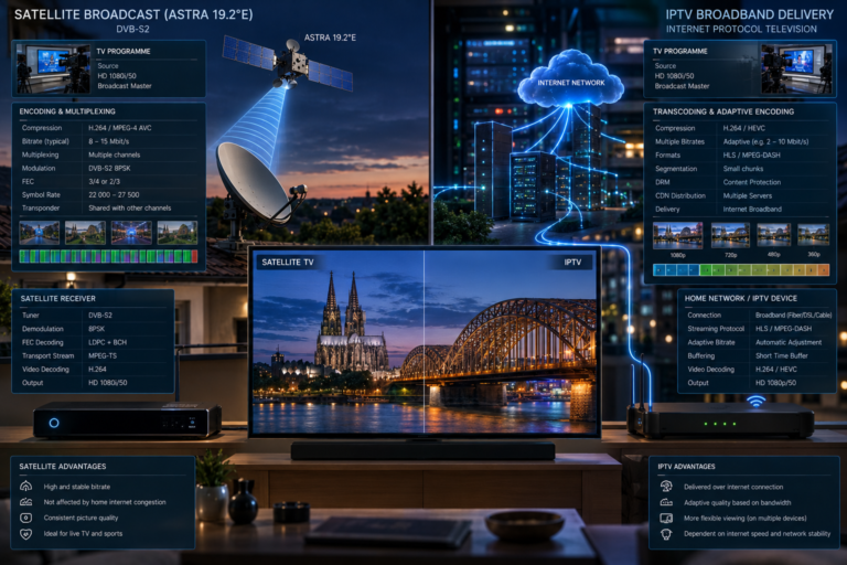
Two transponders from the same orbital position may use completely different technical parameters. One might use horizontal polarization while another uses vertical polarization. One might use QPSK while another uses 8PSK. Their symbol rates and FEC coding rates may also differ.
They may even be transmitted through different satellite beams or different payload hardware.
This is the first reason why comparing frequencies simply because they belong to the same orbital position can be misleading.
Why Transponder Power Can Be Different
Satellite transponders are designed to deliver sufficient power across their intended coverage area, but received power is not necessarily identical across every carrier.
Different transponders may operate through different payload chains, amplifiers, frequencies, and beam configurations. The resulting effective isotropic radiated power can therefore vary across the satellite service.
A stronger transponder produces more carrier energy at the receiving dish and generally provides greater margin against noise and atmospheric attenuation.
A weaker transponder may still work perfectly in clear conditions but operate much closer to the receiver’s decoding threshold.
This becomes obvious during rainfall. The weaker frequency may disappear first while stronger transponders continue working normally.
How Satellite Beam Coverage Changes Reception
Modern satellites often use multiple antenna beams rather than illuminating every location with identical power.
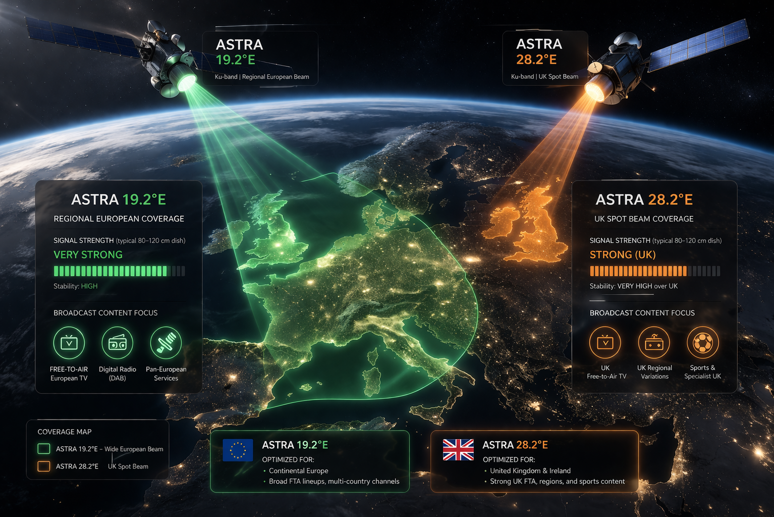
A broad European beam may provide strong coverage across a large region, while another beam may concentrate energy toward a specific country or group of countries.
If your location sits near the centre of a beam, the corresponding transponders may be very easy to receive.
If another frequency belongs to a beam whose edge passes near your location, its available margin may be significantly smaller.
This means two frequencies transmitted from what appears to be the same satellite position can have very different reception performance because their coverage footprints are different.
Why Frequency Itself Can Affect the Receiving Chain
A satellite installation does not have perfectly identical performance at every frequency.
The reflector, feedhorn, LNB, coaxial cable, switches, connectors, and receiver tuner all have frequency-dependent characteristics.
A correctly designed system should operate across its full intended band, but small variations in gain and loss are normal.
These differences usually remain invisible when signal margin is large. They become much more important when a transponder is already close to its decoding threshold.
A loss of only a small fraction of the available margin can determine whether a marginal DVB-S2 carrier remains stable or begins producing errors.
Low Band Versus High Band
A Universal Ku-band LNB normally divides the satellite spectrum into low and high bands.
The low band commonly uses a 9.750 GHz local oscillator. The high band commonly uses a 10.600 GHz local oscillator.
The receiver controls band selection using a 22 kHz tone sent through the coaxial cable.
If the LNB’s high-band oscillator or switching circuit develops a fault, frequencies in the high band may disappear while low-band services remain normal.
A 22 kHz control problem can create a similar pattern. The receiver may attempt to tune a high-band transponder while the LNB remains in low-band mode.
This type of fault is often mistaken for a weak satellite frequency when the real problem is within the receiving system.
| Possible Difference | Effect on Frequency | Typical Symptom |
|---|---|---|
| Lower transponder power | Less carrier margin at dish | Fails earlier during rain |
| Different satellite beam | Lower EIRP at receiving location | One group of channels is consistently weaker |
| Higher cable attenuation | Lower IF level at receiver | Upper IF frequencies may perform worse |
| LNB band-switching fault | Wrong local oscillator selected | Low band works while high band fails |
| Incorrect LNB skew | More cross-polarization interference | Some polarizations show poor MER |
| More demanding MODCOD | Higher decoding requirement | Good strength but unstable DVB-S2 lock |
| Local RF interference | Specific frequency region contaminated | Selected transponders show high BER |
How Coaxial Cable Loss Changes With Frequency
Coaxial cable does not attenuate every frequency by exactly the same amount.
Loss normally increases as frequency rises. This means the higher end of the satellite intermediate-frequency range can experience more attenuation than the lower end over the same cable length.
On a short, good-quality cable, the difference may have little practical effect.
On a long run using ageing or low-quality coaxial cable, the additional loss can become significant.
A transponder converted to a higher IF frequency may therefore arrive at the receiver with less level than another transponder converted to a lower IF frequency.
This is especially relevant in installations containing long cable runs, multiswitches, wall plates, and multiple connectors.
Why LNB Response Is Not Perfectly Flat
An LNB is designed to provide useful gain across a wide frequency range, but real RF amplifiers and filters do not have perfectly flat response.
Small gain variations can exist across the band. Noise performance may also vary slightly with frequency.
A healthy LNB should remain within its design specification, so these variations should not normally cause severe channel differences.
Ageing or faulty electronics can make the variation much larger.
An LNB may therefore perform well at one part of the spectrum while showing reduced gain, increased noise, or oscillator problems elsewhere.
Testing multiple known transponders across the band is more useful than judging an LNB from one strong frequency.
Polarization Can Make One Frequency Look Weaker
Satellite systems reuse spectrum by transmitting carriers on different polarizations.
If horizontal and vertical signals were received without sufficient isolation, transponders using similar frequencies would interfere with each other.
The LNB therefore selects one polarization while attempting to reject the other.
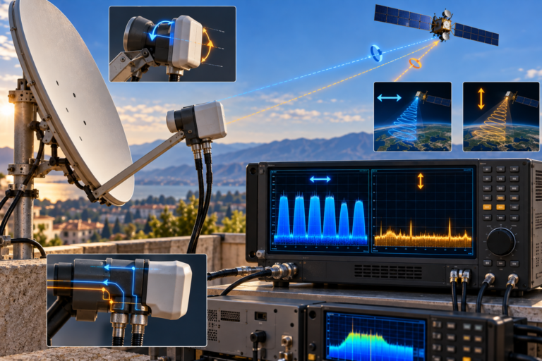
Electrical control from the receiver changes the polarization state, while physical LNB skew aligns the feed correctly with the satellite’s polarization geometry.
A voltage fault can prevent the correct polarization from being selected. Incorrect skew can reduce the isolation between wanted and unwanted signals.
The result may be that one group of frequencies performs far worse than another even though the dish is pointed correctly.
How LNB Skew Changes Transponder Quality
LNB skew affects the relationship between the feed probes and the polarization orientation arriving from the satellite.
When skew is optimized, the wanted polarization is received strongly while the opposite polarization is suppressed as much as possible.
When skew is wrong, cross-polarized energy behaves as additional interference.
Signal strength may remain high because the receiver still detects substantial RF power. MER, however, can fall significantly.
This is why one transponder may appear weak even though the real problem is not insufficient carrier power but excessive interference from the opposite polarization.
QPSK and 8PSK Do Not Need the Same Conditions
Two frequencies can arrive with similar RF power but require different signal quality for successful decoding.
QPSK uses four main constellation states. 8PSK uses eight states and therefore carries more bits per symbol.
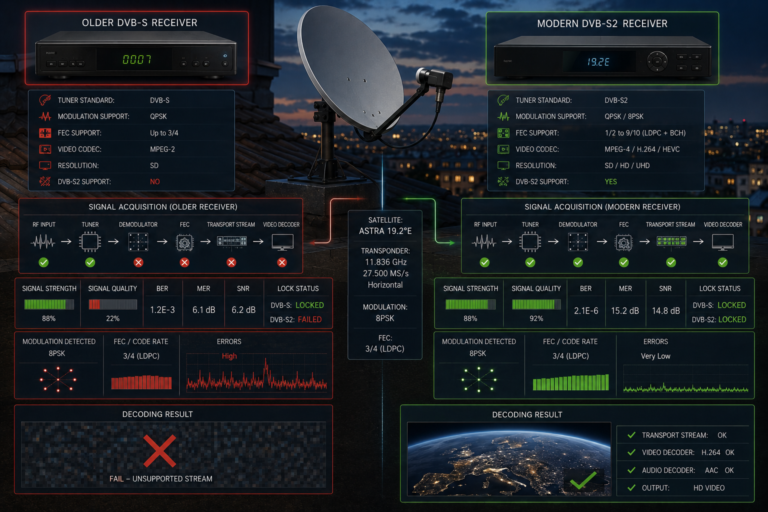
Because 8PSK places its constellation points closer together, the receiver generally requires cleaner symbol separation to make reliable decisions.
This means an 8PSK carrier can fail while a QPSK carrier from the same satellite remains stable.
The difference is not necessarily that the 8PSK transponder is weaker. Its decoding requirement may simply be more demanding.
How FEC Changes the Decoding Threshold
Forward Error Correction adds redundancy that allows the receiver to repair transmission errors.
More robust coding provides greater protection but reduces the proportion of transmitted capacity available for payload data.
A more aggressive coding rate increases efficiency but requires better reception conditions.
The receiver therefore sees each combination of modulation and coding as a different operating requirement.
An 8PSK transponder with one FEC configuration may need significantly better carrier quality than a QPSK transponder with stronger protection.
This modulation and coding combination is often described as the MODCOD.
Why Symbol Rate Matters
Symbol rate describes how many modulation symbols are transmitted each second.
A high symbol-rate carrier occupies more bandwidth than a lower symbol-rate carrier when other conditions are comparable.
Receiver tuner and demodulator performance can vary across extremely wide or narrow signal bandwidths, particularly on older hardware.
Low-symbol-rate carriers can sometimes be more difficult for certain receivers to acquire accurately, while very wide carriers may expose tuner or filter limitations.
Symbol rate does not by itself determine whether a transponder is strong or weak, but it forms part of the complete reception condition and receiver compatibility requirement.
Local Interference Can Target Specific Frequencies
Not every weak-looking satellite frequency is weak at the satellite.
Local interference can affect only part of the intermediate-frequency spectrum between the LNB and receiver.
Poor cable shielding, damaged connectors, unsuitable wall plates, electronic equipment, power supplies, wireless transmitters, and distribution amplifiers can introduce unwanted energy.
If that interference overlaps a converted satellite frequency, MER falls and BER rises on the affected carrier.
Other transponders outside the contaminated frequency range continue working normally.
This frequency-selective behaviour is one reason replacing the dish immediately is often the wrong troubleshooting step.
Why Dish Alignment Affects Transponders Differently
Dish misalignment usually reduces performance across the satellite position, but the effect becomes visible first on carriers with the least existing margin.
A powerful QPSK transponder may continue showing excellent quality even after the dish moves slightly.
A weaker regional-beam transponder using 8PSK may already be close to the digital threshold and begin pixelating immediately.
The viewer therefore concludes that one frequency is faulty when it is actually acting as the first indicator of a broader alignment problem.
Professional alignment should include several representative transponders rather than maximizing only the strongest carrier.
How BER and MER Reveal the Real Difference
Signal strength alone cannot explain why two frequencies behave differently.
MER reveals how accurately the receiver sees the modulation constellation. BER reveals how many bit errors result from imperfect symbol recovery.
Two carriers can show similar strength while one has significantly worse MER because of interference, polarization leakage, phase noise, or a more marginal beam.
The weaker-quality carrier then produces higher pre-FEC BER and consumes more of the Forward Error Correction capability.
Once its remaining margin disappears, post-FEC errors create pixelation or complete loss of lock while the other transponder continues operating normally.
How to Troubleshoot Weak Frequencies Logically
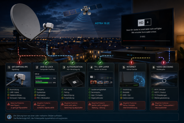
Begin by identifying which frequencies fail and looking for a pattern.
If every high-band transponder fails, test the LNB’s 22 kHz switching and high-band oscillator operation. If one polarization performs poorly, inspect receiver voltage, cable voltage drop, switches, and LNB skew.
If problems occur mainly at the high end of the receiver’s IF range, test the coaxial cable and distribution losses.
Compare MER and BER on strong and weak transponders. If the weak frequency has low MER despite reasonable power, investigate interference, alignment, polarization isolation, or LNB quality.
Test the receiver directly at the LNB with a short known-good cable where practical. This helps separate antenna and LNB performance from losses introduced by the distribution network.
Also verify the actual modulation, symbol rate, FEC, and beam used by the affected transponder. A frequency requiring a more demanding MODCOD should not be expected to behave identically to a robust nearby carrier.
When troubleshooting these differences, it is useful to understand that a high receiver percentage represents only part of the picture. Our guide explaining why your receiver shows 90% signal but no picture shows how RF power can remain high even when the receiver cannot recover a usable digital service.
A frequency that is difficult to receive is not automatically being transmitted with less power.
The difference can come from beam coverage, modulation, FEC, polarization interference, LNB response, cable attenuation, local interference, receiver compatibility, or reduced dish alignment margin.
Likewise, one strong transponder does not prove that the entire installation is correctly optimized. The weakest important carriers are often more useful for exposing alignment and distribution problems.
Some satellite frequencies work better than others because every transponder operates through its own combination of RF power, beam coverage, polarization, symbol rate, modulation, Forward Error Correction, and reception margin.
The receiving system also changes the result. LNB gain and noise performance vary across the band, coaxial cable loss increases with frequency, switching problems can affect one band, incorrect skew can damage one polarization, and local interference can target a narrow frequency range.
The correct way to compare transponders is therefore through MER, BER, signal margin, modulation, FEC, polarization, beam coverage, and the complete RF path rather than signal strength alone.
When one frequency fails while another remains perfect, that difference is often a valuable diagnostic clue. It tells you which part of the satellite or receiving system should be investigated next.
| Question | Answer |
|---|---|
| Why is one satellite frequency stronger than another? | Different transponders can use different powers, beams, polarizations, modulation settings, and coding rates, while the receiving system also has frequency-dependent performance. |
| Does every transponder on one satellite use the same beam? | No. Some satellite positions use multiple beams with different coverage footprints and received power levels. |
| Why do high-band frequencies sometimes fail? | Possible causes include 22 kHz switching faults, high-band LNB oscillator problems, cable loss, or frequency-specific equipment faults. |
| Can coaxial cable make some frequencies weaker? | Yes. Cable attenuation generally increases with frequency, so long or poor-quality runs can affect higher IF frequencies more strongly. |
| Can an LNB work well on some frequencies and badly on others? | Yes. LNB response is not perfectly flat, and faults can affect specific frequency ranges or one local oscillator band. |
| Why does one polarization have lower quality? | Incorrect skew, receiver voltage problems, cable voltage drop, switching faults, or cross-polarization interference can affect one polarization more than another. |
| Why does 8PSK sometimes fail when QPSK still works? | 8PSK uses more closely spaced constellation states and generally requires cleaner reception under comparable coding conditions. |
| Does higher symbol rate mean stronger signal? | No. Symbol rate describes how rapidly symbols are transmitted. It does not directly describe received carrier power. |
| Can interference affect only one satellite frequency? | Yes. Local interference can contaminate a limited frequency region while other transponders remain unaffected. |
| Can dish misalignment affect one transponder first? | Yes. The transponder with the smallest existing margin usually reveals alignment loss before stronger or more robust carriers. |
| Should I align the dish using the strongest frequency? | Not exclusively. Several representative transponders should be checked, including weaker services, both polarizations, and different parts of the band. |
| Which measurements are best for comparing frequencies? | MER, BER, signal quality, and available decoding margin are more informative than raw signal strength alone. |